This is a quick guide that will outline what you need to do in order to install
JiffyDOS v6.01 on your flat C-128 (the D model requires a different procedure).
First, grab the ROM images:
JiffyDOS ROM images
These two binary files have been created for use with a 27C256 or 27256
EPROM. The C-128 image consists of both the JiffyDOS 128 code and the
original Commodore 128 Kernal ROM (P/N 318020-05). The C-128 Kernal provided
is the last release for the 128 Flat model.
The C64 image consists of the JiffyDOS 64 Kernal, C-64 BASIC and the C-64
Kernal. The BASIC/Kernal P/N is 251913-01.
You'll need two 27C256 or 27256 EPROMS. I use 27C256-15 (150ns) parts in my
machines. A good source of these is Unicorn Electronics.
You'll also need an SPST switch, some 24ga wire and two 4.7K, 1/4 watt carbon
resistors. You can find these at Radio Shack in packs of 5 for .99.
After you've programmed the EPROMS (if you don't have a ROM programmer, you
can probably find someone to help you out on the #c64friends channel on
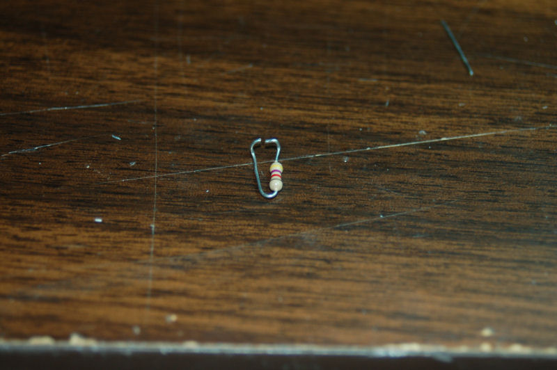
irc.eskimo.com), bend your two 4.7 resistors into this shape:
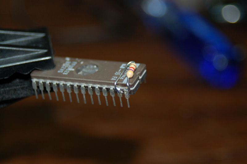
 You're then going to set it on top of the EPROM so that the legs of the
resistor clamp pins 27 and 28. Tape the resistor to the top of the chip
and solder it into place:
You're then going to set it on top of the EPROM so that the legs of the
resistor clamp pins 27 and 28. Tape the resistor to the top of the chip
and solder it into place:
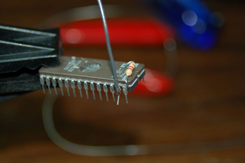
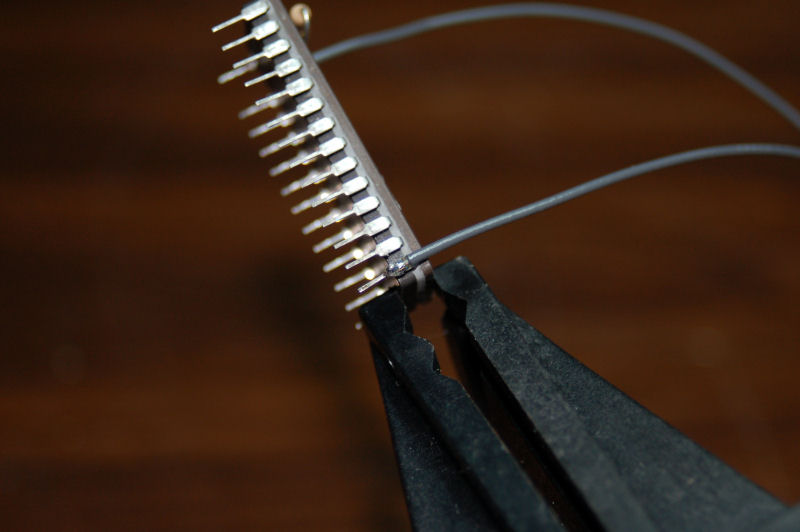
 Next, install a wire on pin 27:
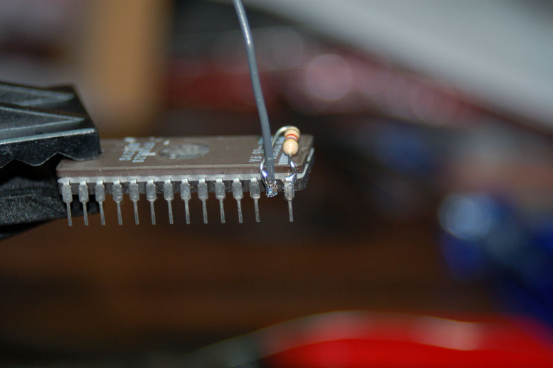
 Now you want to carefully clip pin 27 to prevent it from touching the socket
on the 128:
Now you want to carefully clip pin 27 to prevent it from touching the socket
on the 128:
 You're nearly done!
Now you need to solder a wire to the ground pin on the EPROM (pin 14) like
this:
You're nearly done!
Now you need to solder a wire to the ground pin on the EPROM (pin 14) like
this:
 Perform these steps again for the other EPROM.
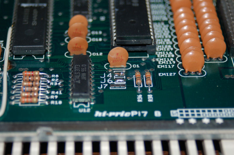
The C-128 EPROM replaces the chip at location U35. The C-64 EPROM replaces
the chip located at U32.
Now you need to close the jumper J6. This jumper is located at the bottom
right hand corner of the board. This will allow the socket for the C64
EPROM to use a 27256. By default (J6 open) it's configured for a 27128.
Perform these steps again for the other EPROM.
The C-128 EPROM replaces the chip at location U35. The C-64 EPROM replaces
the chip located at U32.
Now you need to close the jumper J6. This jumper is located at the bottom
right hand corner of the board. This will allow the socket for the C64
EPROM to use a 27256. By default (J6 open) it's configured for a 27128.
 Now go ahead and install the two EPROMS. Be very careful to make sure that
none of the pins get bent when you're installing the chips. Also, make sure
the notch at the end of the chip is pointed "down" or facing the edge of the
board that does NOT have the user port, video, etc connectors on it.
Take the two wires from the ground pins (pin 14) and twist them together.
Solder them to the center or "common" pin on the switch. Do the same with
the Pin 27 address wires and solder them to the other pole of the switch.
For switch location, please refer to the JiffyDOS Installation Guide.
That's all there is to it.
Now go ahead and install the two EPROMS. Be very careful to make sure that
none of the pins get bent when you're installing the chips. Also, make sure
the notch at the end of the chip is pointed "down" or facing the edge of the
board that does NOT have the user port, video, etc connectors on it.
Take the two wires from the ground pins (pin 14) and twist them together.
Solder them to the center or "common" pin on the switch. Do the same with
the Pin 27 address wires and solder them to the other pole of the switch.
For switch location, please refer to the JiffyDOS Installation Guide.
That's all there is to it.